
UTV Auxiliary Battery Wiring Guide for Trails
Posted by Drew Cummings on Oct 23rd 2026
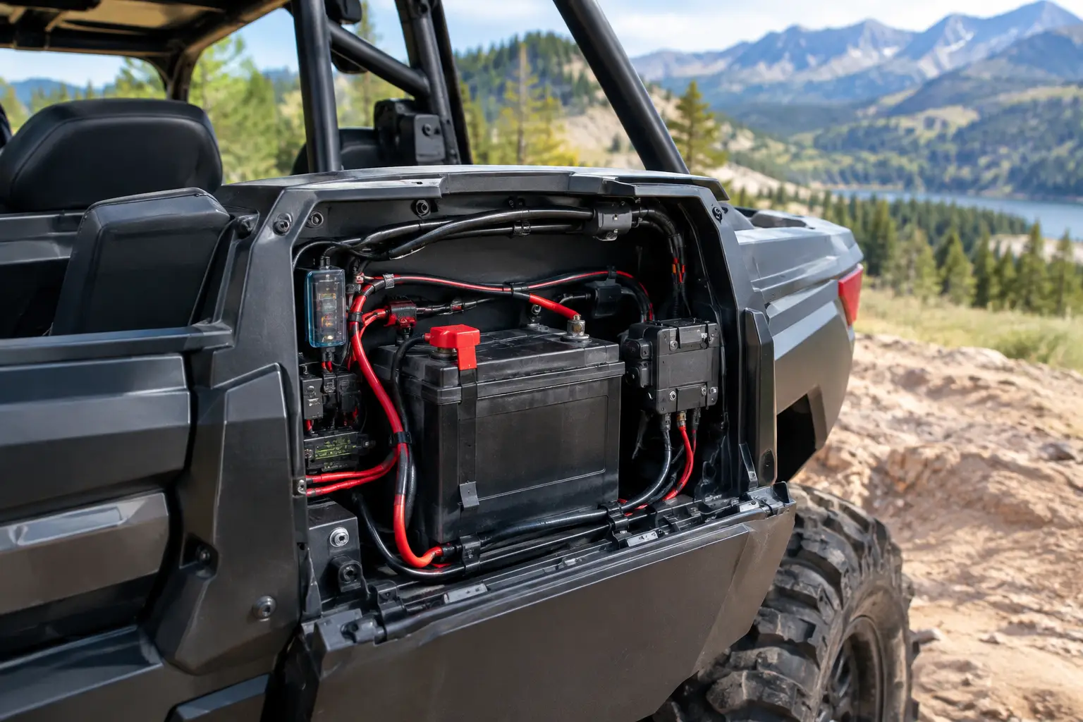
A winch pull at dusk, a cab heater on a freezing hunt, and a light bar running back to camp can drain a single starting battery faster than most riders expect. This UTV auxiliary battery wiring guide lays out how to add reserve power without creating hard-start issues, overheated cables, or a wiring mess that fails when the trail gets rough.
The goal is simple: keep the starting battery ready to start the engine, while giving high-demand accessories their own protected power source. The right layout depends on your machine, accessory load, battery location, and how you ride, but the core electrical rules stay the same for Polaris, Can-Am, Yamaha, Kawasaki, and Honda side-by-sides.
Start With the Accessory Load
Do not choose a second battery or cable size based on what looks right under the hood. Start by totaling the accessories you expect to run at the same time. Common auxiliary loads include light bars, whips, audio amplifiers, heaters, communication radios, GPS units, sprayers, refrigerators, and charging ports.
Watts divided by system voltage gives a close estimate of amperage. A 120-watt light bar on a 12-volt system draws roughly 10 amps. An amplifier rated at 500 watts can draw far more than its casual listening load suggests, especially at volume. A winch is a separate case: its intermittent draw is extremely high, and it normally belongs on the primary battery or a purpose-built dual-battery system with cables sized for the winch manufacturer’s requirements.
Add the loads you will actually use together, then leave room for expansion. If your planned accessories total 35 amps, designing a 40-amp system is tight. A 60-amp capable auxiliary circuit gives better margin, provided the battery, isolator, cables, fuses, and distribution block are all sized to match.
Choose a Dual-Battery Layout That Fits Your UTV
Most UTV auxiliary battery installations use two batteries connected through an isolating device. With the engine running, the charging system replenishes both batteries. With the key off, the isolator separates them so a cooler, sound system, or camp lights cannot pull down the battery needed to start the machine.
A voltage-sensitive relay, also called an automatic charging relay, is a popular choice for many recreational UTV builds. It connects the batteries when charging voltage rises and separates them when voltage drops. It is straightforward and works well for accessory batteries that are similar in chemistry and capacity to the starting battery.
A manual battery switch is simpler but depends on the operator remembering to switch it on and off. It can work for a basic ranch or hunting rig, but it is less forgiving after a long day in the field.
A DC-to-DC charger is the better option when the auxiliary battery uses a different chemistry, particularly lithium, or when the second battery is mounted far from the charging source. It provides controlled charging and helps prevent an alternator from being asked to charge a battery in a way it was not designed to handle. The trade-off is added cost, wiring complexity, and space requirements.
Before buying anything, confirm the available charging output for your exact year and model. Factory stator output is not the same as the usable electrical capacity after the engine, fuel system, factory lights, cooling fans, and electronics take their share. High-output accessory builds may need a charging-system upgrade, reduced accessory use at idle, or a battery bank that is recharged externally between rides.
Parts That Should Be Matched, Not Mixed
A reliable system is more than a second battery and a few wires. Build around components rated for the actual current and environment:
- A properly secured auxiliary battery and model-specific mounting tray
- A battery isolator or DC-to-DC charger matched to battery chemistry and amperage
- Marine-grade or automotive-grade stranded copper cable sized for cable length and load
- Main fuses or circuit breakers located close to each battery positive terminal
- A sealed fuse block or power distribution panel for individual accessory circuits
- Crimp terminals, heat-shrink, loom, grommets, clamps, and abrasion protection
Avoid undersized aluminum-clad cable, household wire, open terminal blocks, and unsealed connectors. UTVs deal with vibration, water crossings, mud, washdowns, and constant temperature swings. A wiring setup that survives only in a dry garage is not a trail-ready setup.
UTV Auxiliary Battery Wiring Guide: Basic Circuit Layout
The safest layout keeps protection close to the power source. Run a fused positive cable from the starting battery to the isolator or charger input. From the isolator or charger output, run another fused positive cable to the auxiliary battery. Ground the auxiliary battery with a cable sized to match the positive lead, either to a verified chassis ground point or directly back to the starting battery negative terminal.
From the auxiliary battery, feed a fused distribution block. Every accessory then gets its own correctly sized fuse, switch or relay control, positive wire, and ground path. This makes troubleshooting far easier than stacking accessory ring terminals directly on a battery post.
Place the primary fuse within several inches of each battery’s positive terminal whenever practical. That fuse protects the cable if it gets pinched against the frame, rubbed through under a seat base, or damaged in an impact. A fuse located several feet away may protect the accessory, but it leaves too much unfused cable exposed.
For most moderate-distance runs, 8 AWG or 6 AWG cable is common for an auxiliary supply circuit, but there is no universal wire size. Current, wire length, allowable voltage drop, and future loads decide the answer. A short 30-amp run needs less cable than a long 60-amp run from a front-mounted battery to a rear cargo-area power panel. Follow the ratings supplied with your isolator, charger, fuse block, and accessories, then size the main feed for the weakest safe limit in that circuit.
Route Cables for Movement, Heat, and Service
A clean routing path is not just for appearance. Keep cable away from exhaust components, turbo heat where applicable, steering shafts, drive belts, suspension travel, sharp frame edges, and areas where seats or cargo panels can crush it.
Use split loom or braided sleeve anywhere wiring may contact the chassis. Add rubber grommets where cables pass through panels. Secure the harness at regular intervals with quality clamps or mounts, leaving enough slack at points where the engine, bed, or suspension moves. Zip ties are useful for organizing, but they should not be the only support on a high-current cable run.
Pay special attention to battery mounting. The battery tray must hold the battery securely over rough terrain, and the terminals need protection from tools, cargo, and accidental contact. If you use a rear-mounted auxiliary battery, plan for water exposure and make sure the enclosure does not trap moisture around terminals.
Wire High-Draw Accessories the Right Way
A fuse block simplifies smaller loads, but not every accessory should be powered the same way. Lights, radios, chargers, and switches generally work well from a protected distribution panel. High-draw audio equipment may require its own fused supply. Winches require dedicated heavy-gauge cables, a properly rated contactor, and a battery setup designed for their demand.
Use relays for accessories that draw more current than a dash switch should carry. A small switch can trigger the relay, while the relay handles the larger accessory current through properly sized wire. This reduces voltage drop and protects factory switches and delicate control wiring.
For keyed accessories, use an ignition-triggered signal to control a relay rather than pulling accessory power from a small factory ignition wire. The factory circuit should provide a signal, not become the main power feed for added equipment.
Test the System Before the First Ride
With the engine off, verify that the starting and auxiliary batteries are isolated when they should be. Turn on auxiliary accessories and confirm the starting battery voltage remains stable. Then start the UTV and verify that the isolator or charger connects and both batteries receive charging voltage according to the component manufacturer’s specifications.
Check every fuse value against wire size and accessory requirements. Feel the main cables and terminals after running a meaningful load for several minutes. Warm is not automatically a problem, but hot connections, a burning smell, dimming lights, or repeated blown fuses mean stop and correct the issue before riding.
Label fuses and take a photo of the finished routing before reinstalling panels. Months later, when adding a heater, replacing a light, or tracking down a loose ground, that small step saves real time.
A well-planned auxiliary battery system gives your UTV more working range without gambling with the next engine start. Build it around your actual loads, protect every power source, and use fitment-specific mounting and wiring components that can take the same punishment as the rest of your machine.