
Turn Signal Kit Installation for Your UTV
Posted by Drew Cummings on Jul 20th 2026
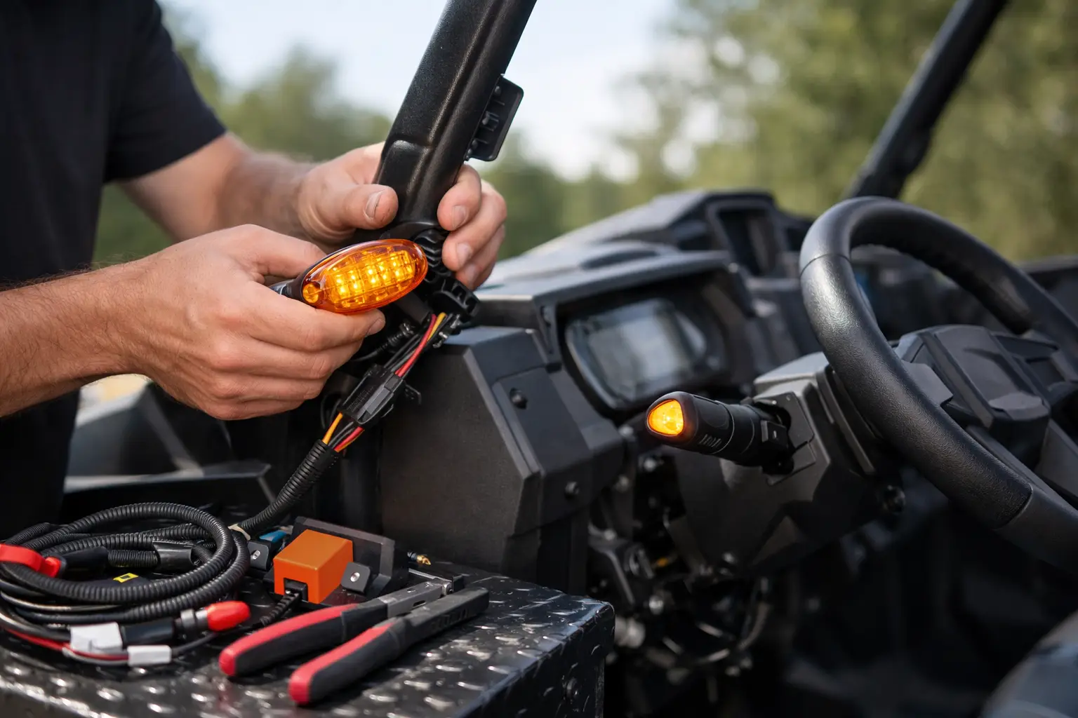
A turn signal kit installation is one of those upgrades that looks simple from the driver’s seat but can become a wiring headache if the kit does not match your machine. The right setup adds clear signaling for group rides, public-road connections where permitted, ranch work, and low-light travel. The wrong setup can mean loose wires, failed flashers, dim indicators, or a kit that never fits your dash correctly in the first place.
For Polaris, Can-Am, Yamaha, Kawasaki, and Honda owners, the best starting point is not the lowest-priced universal kit. Start with a kit built around your exact UTV model, year, and factory electrical system. That choice usually saves more time than any shortcut during installation.
Start With Fitment Before Opening the Box
A turn signal system has to work with several parts of your UTV at once: the vehicle’s voltage, dash layout, harness routing, lighting configuration, and often its brake-light circuit. A model-specific kit is designed around those details. It may include a plug-and-play harness, dash switch mount, labeled leads, and connectors that match factory plugs.
Universal kits can still be useful, especially on older machines, custom builds, or UTVs with heavily modified lighting. The trade-off is that you may need to identify wires yourself, cut into factory circuits, add terminals, and fabricate a mounting location. That is manageable for an experienced installer, but it takes more planning and creates more opportunities for a poor connection.
Before ordering or installing, verify the full vehicle information: manufacturer, model, year, trim, and whether it has factory LED headlights or taillights. Also account for doors, a roof, windshield, cab enclosure, aftermarket bumpers, and audio accessories. These upgrades can change where you mount lights and how you route wiring.
Road-use rules are not the same everywhere. Some states, counties, and public-land areas require additional equipment beyond turn signals, such as mirrors, a horn, a license plate light, reflectors, or a DOT-compliant windshield. Check the rules that apply where you plan to ride before treating a signal kit as a complete street-legal conversion.
Tools and Prep That Prevent Wiring Problems
Most model-specific kits include the primary hardware, but a clean install still calls for basic shop tools. Have a socket set, screwdrivers, trim tools, wire cutters, crimpers, drill and bits if required, electrical tape, heat-shrink tubing, and dielectric grease on hand. A multimeter is worth having even with plug-and-play wiring. It helps confirm power, ground, and brake-light behavior before you button up the machine.
Park on level ground, set the brake, remove the key, and disconnect the negative battery terminal. If your UTV has a battery disconnect switch, use it, but still verify that the accessory circuits are dead. Do not rely on the ignition being off alone.
Remove only the body panels needed to access the battery, factory taillight harness, and intended switch location. Keeping panels organized by side and hardware type makes reassembly much faster. Take a few photos of factory wire routing before moving anything. They are useful if you need to verify clamp locations or keep the new harness away from hot exhaust components and moving suspension parts.
Turn Signal Kit Installation: Mount the Components First
Dry-fit the components before connecting wires. This includes the turn signal switch, front marker lights or signal pods, rear signals, horn button if included, flasher module, and dash indicator lights. Look at the machine from the driver’s seat and from several yards away. The switch should be easy to reach without releasing the steering wheel for long, and the lights should be visible from the intended direction.
Front signals are commonly mounted near the headlights, on the front fascia, or on a bumper bracket. Rear signals may mount near the taillights, on the bed, or on a rear bumper. Keep them protected from branches and rocks, but do not tuck them so far inward that they become difficult to see.
When drilling is necessary, confirm what sits behind the panel before making a hole. A clean mounting hole in visible plastic is easy. Drilling into a hidden harness, radiator line, or structural support is not. Use the supplied templates if available, start with a small pilot hole, and protect exposed drilled edges where wiring passes through with a grommet.
Route the Harness Like It Has to Survive the Trail
A turn signal harness should follow protected factory routes whenever possible. Run it along the frame, under console panels, or beside existing electrical looms. Use factory clips when they are available and secure the harness with quality zip ties at regular intervals.
Avoid four common routing mistakes:
- Leaving wire loose near driveshafts, axles, steering shafts, or suspension travel
- Running wire directly against exhaust parts, sharp metal edges, or unprotected brackets
- Pulling the harness tight enough that full steering or suspension movement stresses it
- Installing connectors where they constantly collect water, mud, or pressure-washer spray
Leave a small service loop near lights and switches so a component can be replaced without reworking the entire harness. That extra inch or two of wire matters when a rear light gets damaged on a tight trail.
At each connector, make sure the plug is fully seated and locked. If you are making crimped connections, use proper automotive-grade terminals and heat-shrink, not household wire nuts or a quick wrap of tape. Apply a light amount of dielectric grease to sealed connectors to help limit moisture intrusion. Grease does not repair a bad connection, but it helps protect a good one.
Connect Power, Ground, and Brake Inputs Carefully
Most kits need a fused 12-volt power source, a solid ground, and connections to the left and right rear lighting circuits. Kits with brake integration also connect to the brake-light input, allowing the rear lamps to flash correctly while preserving brake-light function.
Follow the kit’s wiring diagram exactly. Wire colors vary by manufacturer and can also vary between model years. Never assume a red wire on the UTV harness is always switched power or that a black wire is always ground. Confirm circuits with a multimeter or the vehicle’s service information.
Ground issues cause many signal-kit complaints. A weak ground can produce intermittent flashing, a glowing indicator when the system is off, or lights that work only when another accessory is running. Use the designated ground point when the kit provides one. If you must create a new chassis ground, use bare, clean metal, a secure fastener, and corrosion protection after the connection is tightened.
LED lighting can introduce another variable. LEDs draw less current than incandescent bulbs, so a standard flasher relay may hyperflash or fail to cycle. Many UTV-specific kits include an LED-compatible flasher. If yours does not, confirm whether it requires a compatible relay, load resistors, or a different wiring approach before final assembly.
Test Every Function Before Reinstalling Panels
Reconnect the battery and test the system before securing every panel and zip tie. Start with the key in the required position and check left turn, right turn, hazards, dash indicators, front lights, rear lights, and brake-light operation. Walk around the UTV while each function is active rather than checking only from the seat.
Pay attention to how the rear lights behave with the brake applied. On combination brake-and-turn systems, activating a turn signal while holding the brake should still provide a clear flashing signal on the selected side. If both rear lamps flash, the indicators are reversed, or the brakes stop working properly, disconnect power and revisit the wiring diagram before riding.
Then turn the steering wheel from lock to lock and inspect the front harness. Cycle the suspension if practical, or at least inspect areas near the shock travel and A-arms. Confirm that wires are not pinched when the hood, seats, storage compartments, or body panels are reinstalled.
Finish the Install for Long-Term Reliability
Once the system passes testing, secure the harness permanently. Trim zip-tie tails flush so they do not snag gloves, wiring, or skin during future service. Reinstall panels without forcing them over a harness. If a panel will not sit correctly, stop and find the interference instead of tightening the fasteners harder.
After the first few rides, inspect the mounting hardware and connector locations. Rough terrain can reveal a wire that looked properly secured in the garage but rubs when the chassis flexes. Check again after muddy rides, deep water crossings, or pressure washing around the rear bed and front fascia.
A properly fitted kit gives your UTV a more useful, safer setup without turning routine maintenance into a wiring project. If you are selecting components, Side By Side Sports can help narrow the options by make, model, and intended use so you can start with equipment designed for your machine. Take the extra time to protect the wiring now, and your signals will still be working when the trail gets rough.